項(xiàng)目-幻燈片1.jpg)
When electrical equipment is in use, due to the thermal effect of conductor resistance, electrical components and circuits will generate heat; Due to the normal operation of electrical components such as switches and relays, electrical sparks or arcs may occur when the circuit is turned on or off; Due to insufficient insulation or spacing between electrical components, conductive parts with different potentials may experience faults such as short circuits, breakdowns, and generate heat, electrical sparks, or arcs. These may only cause equipment failures, line failures, etc. in ordinary environments, but in explosive environments, they may ignite explosive substances and explode. Therefore, it is necessary to take measures to prevent electrical equipment from causing explosion accidents.
The most direct measure is to install electrical equipment inside a sufficiently sturdy casing without considering the working principle and power size of the equipment. Even if the electrical equipment causes an explosion of explosive substances around it, the high temperature and high pressure generated by the explosion will not spread throughout the environment due to being wrapped in the casing, thus avoiding more serious consequences.
Therefore, this shell should first have sufficient strength to withstand the pressure generated by internal explosions. In GB/T 3836.2 "Equipment protected by explosion-proof shell" d "in explosive environments", the explosion-proof shell needs to withstand at least 1.5 times the internal explosion pressure.
In addition, when the equipment is used in explosive environments, the casing itself should not become an ignition source. During long-term operation, the external surface of the equipment should not have high temperatures sufficient to cause ignition. Even if the high temperature inside the device causes ignition, it cannot be transmitted to the outside, so there is no need to consider its ignition risk. However, it should be prevented to open the cover immediately after power failure. The temperature of the high-temperature surface has not yet dropped below the minimum ignition temperature. Therefore, it is necessary to apply warning signs outside the shell and open the cover plate after sufficient power failure.
When the shell is made of metal material, if it is subjected to external impact or friction, mechanical sparks may be generated, causing ignition. Light metals such as aluminum, magnesium, titanium zirconium, etc. are prone to generate high-temperature mechanical sparks when collided with rusted iron. Therefore, the proportion of light metal components in the metal shell material should be strictly controlled. It should be noted that although copper and copper alloys do not ignite in most cases and do not produce high-temperature mechanical sparks when collided with other metals, they are often used as explosion-proof tools. However, copper can form acetylene compounds with acetylene, which will burn violently after friction and collision. Therefore, if the equipment is expected to be used in an environment with acetylene, the copper content of the shell material should be controlled to not exceed 65%.
The casing should also have sufficient stability and should not corrode during daily use. High activity zinc and alloys with zinc content exceeding 80% are not suitable for manufacturing explosion-proof equipment casings.
When the shell is made of non-metallic materials other than glass and ceramics, in addition to considering the performance degradation caused by high and low temperatures during long-term operation, it is also necessary to consider the performance degradation caused by exposure to ultraviolet radiation for transparent lighting fixtures used in coal mines and shells used in non mining areas. In addition, non-metallic materials accumulate static electricity upon friction, and when the static electricity discharges at a sufficiently high potential, it will ignite flammable substances in the environment. Therefore, it is necessary to avoid the generation of static electricity or prevent the accumulation of static electricity. Anti static materials or measures to release static electricity as soon as possible can be chosen to reduce the risk of static electricity ignition.
During the manufacturing and use of electrical equipment, it is inevitable to open the casing for installation, debugging, maintenance, and other work. It is impossible to weld the casing into a completely enclosed whole, which inevitably forms a structure where two different components are joined on the casing. There is a gap at the joint position. In order to prevent explosive flames inside the equipment from spreading from the gap at the joint to the surrounding environment, special design of the joint structure is required. According to existing research, when flames propagate along narrow gaps, the smaller the gap, the lower the energy transmitted to the outside. When the gap is small enough, the internal flame will not be able to ignite the external environment through the joint. In addition, the longer the flame channel, the better the effect of reducing flame energy. In explosion-proof standards, such flame channels are called explosion-proof joint surfaces. Based on extensive testing, safety values for the width and corresponding gap of explosion-proof joint surfaces of different explosion-proof levels have been obtained. When the width of the joint surface is greater than these minimum values and the gap is less than the maximum value, the explosion-proof shell can effectively prevent internal flames from spreading to the surrounding environment of the equipment.
The types of explosion-proof joint surfaces mainly include flat type, cylindrical type, stop type, threaded type, and bonded type. Regardless of the type, it is a channel for internal explosive flames to propagate outward, and in design, the worst-case scenario should be considered.
Due to the variety of fastening methods, the width and distance of the planar joint surface also vary in various positions. The common types include external fixation, internal fixation, and connected cavity fixation.
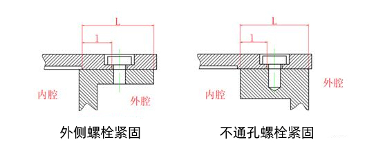
Figure 1 Bolt tightened from the outside
Firstly, let's take a look at the most common structure shown in Figure 1, where the flat cover plate is fastened to the flange from the outside with bolts. In this fastening method, the screw holes may be through holes or non through holes, and the shell may be on the outside or inside of the flange. Although the shape of the screw holes and the position of the shell are different, the explosion-proof parameters are the same. Obviously, in this case, there are two channels for flame propagation: the first one propagates outward along the gap of the entire plane joint surface; The other one propagates along the plane joint surface to the fastening bolt and outward from the bolt hole. Therefore, the explosion-proof surface parameters that need to be controlled for this structure include: the total effective explosion-proof surface joint width, and the distance from the inside of the hole to the edge of the flange. When the screw hole is not connected, attention should also be paid to the requirements of GB/T 3836.2-2021 for bolt head allowance to prevent the bolt from being unable to tighten without a washer.
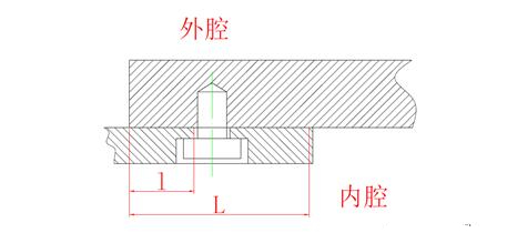
Figure 2: Bolts fixed from the inside
In some cases, it is necessary to fix the cover plate from the inside. For example, in the radiator structure of some frequency converters shown in Figure 2, due to the large heat dissipation fins on the outer cover of the radiator heat pipe, it is not possible to tighten the bolts from the outside. In this case, it is necessary to first fix the radiator substrate on the transition flange from the inside, and then assemble the transition flange onto the explosion-proof shell. In this structure, the propagation channel along the entire plane still exists, but when propagating from the outer edge of the substrate and flange to the bolt, both sides of the channel are inside the shell and there will be no explosion transmission. Therefore, this channel does not need to be designed according to the explosion-proof joint surface, as long as it meets the requirements of the remaining thickness of the explosion-proof shell wall in GB/T 3836.2-2021; But if the flame propagates from the bolt hole along the plane towards the inside of the transition flange, it can reach the outside of the shell and cause an external explosion, so this channel needs to meet the requirements of the explosion-proof joint surface. Through simple analysis, this structure requires controlling the parameters of the explosion-proof surface, including the total effective explosion-proof surface joint width and the distance from the inner edge of the hole to the edge of the transition flange.
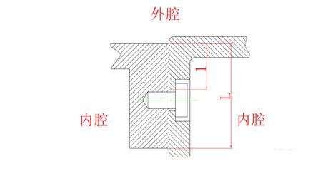
Figure 3 Bolt connection of two connected shells
In other cases, it is necessary to fix the two sections of the housing as shown in Figure 3 together with bolts from the inside, but the two sections of the housing are not separated. For example, for multi circuit combination switches, the housing is very long. For ease of processing, manufacturing units often design it into multiple sections and then assemble them into a complete housing. In this structure, the path of flame propagation is somewhat different from the above situation. When the flame propagates from the bolt hole along the plane to the inside of the flange, the inside is still inside the explosion-proof shell, but when it propagates to the outside of the flange, it will reach the outside of the shell. This channel needs to meet the requirements of the explosion-proof joint surface to ensure that the flame does not propagate to the outside and cause an explosion in the surrounding environment. Therefore, the explosion-proof surface parameters that need to be controlled for this structure are: the total effective explosion-proof surface joint width, and the distance from the outer side of the hole to the flange edge.
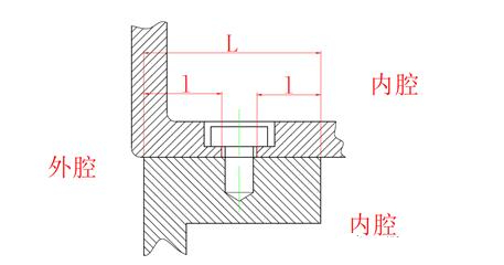
Figure 4 Bolt connection of two separated shells
When there are some changes in this structure, if a flange is needed to connect the two separated shells as shown in Figure 4, different flame channels need to be considered, such as the explosion-proof joint surface between the junction box of the explosion-proof motor and the base. In this structure, flames can propagate from the inside of the flange or from the bolt hole to the outside edge of the flange along the joint surface, which may cause an explosion in the external environment of the explosion-proof shell. At the same time, when flames propagate from the inside of the flange to the bolt hole, it will cause an explosion in another cavity. Therefore, in this case, the width of the joint surface, the distance from the bolt hole edge to the outside edge of the flange, and the distance from the bolt hole edge to the inside edge of the flange all need to meet the requirements of the explosion-proof joint surface.
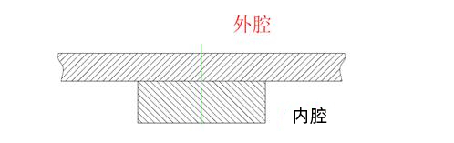
Figure 5: No bolt fastening in the middle of the flange
Sometimes, the flange may be narrow and elongated. In order to reinforce it, the manufacturing company will add a reinforcing flange in the middle, as shown in Figure 5. If there are no fastening bolts on this flange and the cavity is not divided into two parts, then there is no need to design it according to the explosion-proof joint surface.
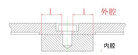
Figure 6: The flanges in the same cavity are fastened with bolts in the middle
However, in some cases, due to the large joint surface, relying solely on peripheral fixation cannot guarantee the strength of the cover plate during explosion. Therefore, there will be fastening bolts on the middle flange, as shown in Figure 6. In this case, the flame channel needs to be considered. Since both sides of the flange are the same cavity, the entire plane joint surface does not need to meet the width of the explosion-proof joint surface. However, if the flame propagates from the flange edge along the joint surface to the edge of the fastening bolt hole, or from the bolt hole to the outside of the shell, this joint surface needs to meet the distance of the explosion-proof joint surface.
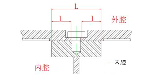
Figure 7: The flanges between different chambers are fastened with bolts
In other cases, two adjacent chambers share a cover plate, as shown in Figure 7. For example, on high-power conveyor motors, the motor chamber and wiring chamber share a cover plate above. In this structure, in addition to the distance from the flange edge to the bolt hole that needs to conform to the distance of the explosion-proof joint surface, if the flame propagates along the entire joint surface, it will also propagate from one cavity to another, causing an explosion in that cavity. Therefore, the effective joint width of the flange needs to meet the width requirements of the explosion-proof joint surface.
In order to display information about electrical equipment or transmit light from a light source to the outside, transparent components need to be installed on the casing, unless expensive materials such as polycarbonate can be drilled or machined to meet the requirements for fixing and dimensional accuracy of the explosion-proof surface. The widely used tempered glass cannot guarantee dimensional accuracy, and other means can only be used to meet the requirements of the explosion-proof joint surface. At present, most mining equipment is installed with pads for easy replacement, but due to the large gap between the joint surfaces, it cannot guarantee passing the non explosion test of internal ignition of Class II equipment. The transparent parts of Class II equipment are basically bonded to the joint surface, and the adhesive in this joint surface generally only ensures the sealing effect. The transparent parts need to be fixed by mechanical structure. At present, there are also special fusion bonding surfaces that melt glass and cast it into the shell or frame, with almost no gap between the glass and metal components. However, this process is costly and generally not used.
Electrical equipment usually has wiring connections with other devices to achieve functions such as power supply, control, and communication. Explosion proof electrical equipment uses cables to achieve these functions. However, as the cable is made of elastic rubber, it cannot be processed into a cylindrical shape with fixed external dimensions like metal or plastic, and the position of the cable after installation should also have sufficient stability to prevent line faults caused by pulling during use. Based on the characteristics of cable materials and structures, a cylindrical sealing ring with holes is generally used to enclose the outside of the cable, and installed together with a metal gasket into the connecting joint. Various compression devices are used to compress the sealing ring axially, causing it to expand radially. Due to the connection joint on the outer side of the sealing ring, the sealing ring can only expand inward, thus tightly combining with the cable and achieving the function of clamping the cable. This structure is called a cable introduction device. For the introduction device used on the explosion-proof shell, in addition to clamping the cable, it should also prevent internal flames from spreading to the environment through the gaps between the sealing ring and the cable, and between the sealing ring and the connecting joint. Therefore, additional sealing tests should be conducted to confirm its ability to prevent flame propagation. For Class IIC equipment or situations where cables are too short, the risk of flame propagation from inside the cable should also be considered. It is generally recommended that the length of the cable outside the explosion-proof enclosure should not be less than 1 meter.
Summary of Explosion proof Shell
The use of explosion-proof enclosures for protection does not require modification or reduction of the performance of electrical components, and there are no restrictions on the types of electrical equipment. It is convenient to apply and is the most commonly used explosion-proof type. However, due to the need for the shell to withstand internal explosive pressure and the bulky structure, it will also increase manufacturing costs.
目 - 2021-11-09T091045 (8).jpg)
目 - 2021-11-09T091045 (7).jpg)
目 - 2021-11-09T091045 (12).jpg)
.jpg)

.jpg)

|
||||||
|
||||||


擊這里給我發(fā)消息")